The problem these terms solve
A model element can look finished without being reliable. A wall drawn at the right thickness in an early design model looks exactly like a wall whose build-up has been fully specified and coordinated. Someone using the model downstream, a consultant, a contractor or an estimator, cannot tell the difference by looking. LOD and LOI give teams a way to say, element by element and stage by stage, how far the content can be trusted.
Level of development versus level of detail
"LOD" is used with two different meanings, and confusing them causes real disputes.
- Level of detail describes how much graphic detail an element shows. A highly detailed element can still be a placeholder.
- Level of development describes how much the element's geometry and information can be relied upon by other users. It is about reliability and decision status, not appearance.
In North America, LOD usually means level of development, following the approach that originated in AIA contract documents and was elaborated in the BIMForum Level of Development Specification. In the United Kingdom and in ISO 19650 practice, the conversation has moved toward the "level of information need", which covers geometry, alphanumeric information and documentation together. Always check which meaning a contract or BEP uses.
The LOD steps in plain language
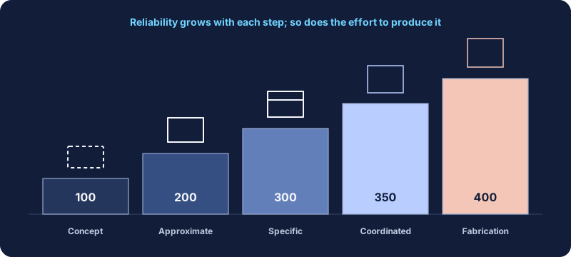
The commonly used steps for level of development, simplified, are:
| Step | What can be relied on | Typical use |
|---|---|---|
| LOD 100 | The element exists, perhaps as a symbol or mass. Size, shape and location are not reliable. | Early massing and area studies |
| LOD 200 | A generic placeholder with approximate size, shape, location and orientation. | Schematic design and early coordination |
| LOD 300 | Specific size, shape, location and orientation can be measured from the model. | Design development and construction documents |
| LOD 350 | As LOD 300, plus the interfaces with other systems needed for coordination, such as supports and connections. | Detailed trade coordination |
| LOD 400 | Enough detail and accuracy for fabrication and installation. | Shop drawings and fabrication |
LOD 500 is also used by some teams to describe field-verified, as-built content. The BIMForum specification treats field verification as a separate matter rather than a further step of development, so define it explicitly if your project uses the term.
This table is a paraphrase for orientation. For contractual use, refer to the specification edition named in your agreement, which contains element-by-element definitions and examples.
LOI and level of information need
LOI, level of information, describes the non-graphical data attached to an element: type, performance values, manufacturer, classification codes, maintenance information and so on. It grew up in UK practice alongside a geometric level of detail.
ISO 19650 practice uses the broader concept of the level of information need, and the European standard EN 17412-1 sets out a framework for specifying it. The idea is to define, for each purpose and exchange, exactly what geometry, what properties and what documents are needed. Not more, not less. This purpose-led approach is helpful even outside Europe, because it starts from the question "what will someone do with this information?"
Using LOD in a responsibility matrix
LOD becomes useful when it is attached to specific elements, stages and responsible parties. A typical matrix has elements in rows and project stages in columns, with each cell giving the target LOD and the party responsible.
| Element | Schematic | Design development | Construction documents |
|---|---|---|---|
| Exterior walls | 200 / Architect | 300 / Architect | 300 / Architect |
| Structural framing | 200 / Structural | 300 / Structural | 350 / Structural |
| Ductwork mains | 100 / Mechanical | 200 / Mechanical | 300 / Mechanical |
| Furniture | Not modeled | 200 / Interiors | 200 / Interiors |
Notice that targets do not rise uniformly. Furniture may never need more than a placeholder. Structural connections might need LOD 350 only where coordination demands it. Setting every element to a high level by default is the fastest way to create unpriced work.
Specifying information, not just geometry
For each element type that carries data, define:
- Which parameters must be filled, and by which stage.
- The data type, units and allowed values.
- Who is responsible for the value, and who verifies it.
- Where the parameter lives: type or instance, shared or project parameter.
- How it will be exchanged, for example which IFC property set it maps to.
Keep the list tied to purpose. If nobody downstream uses a parameter, do not require it. If the owner needs asset data at handover, ask early for the exact fields and format; retrofitting data at the end is painful. The IFC export basics guide covers how parameters travel in open exchanges.
Worked example: one wall through three stages
Consider a synthetic exterior wall on a small office project, followed through three stages.
Schematic design, LOD 200. The architect models a generic exterior wall type with an approximate overall thickness. The type name says "Generic" so nobody mistakes it for a decided build-up. Information is minimal: function and a placeholder fire rating field marked "to be confirmed". The structural engineer can use the wall's location to set out a grid, but should not rely on its thickness for anything critical.
Design development, LOD 300. The wall type is replaced with a specific build-up: layers for cladding, cavity, insulation, sheathing and studs, with thicknesses that can be measured from the model. Information grows to include thermal performance targets and the fire rating, each with a named owner. The mechanical engineer can now rely on the wall's position and thickness when locating penetrations.
Construction documents, still LOD 300. Geometry stays at LOD 300, because the architect does not model individual fixings or panel joints; those are covered by drafting details and specifications. What changes is the information: specification references are added, and the type is checked against the wall schedule. A contractor who later needs panel layouts for fabrication would develop that content to LOD 400 in their own model, under their own responsibility.
The example shows two useful habits. First, geometry and information progress separately; a stage can leave one unchanged while the other advances. Second, the type name and parameters signal status honestly at each stage, so nobody downstream mistakes a placeholder for a decision.
What this means in Revit
- Families should match the target. A highly detailed manufacturer family in an early-stage model can imply reliability you have not reached, and slow the model. A generic family is often the honest choice until a product is selected.
- Mark status where people can see it. Some teams add a parameter recording the element's current LOD or approval status, which can be filtered and scheduled.
- Use view filters to highlight elements below their target for a given stage during internal reviews.
- Check families against the target before they enter the library. The family QA checklist includes this check.
Common pitfalls
- Treating LOD as a single project number. "The model is LOD 300" means little. Elements progress at different rates.
- Confusing appearance with reliability. Detailed graphics do not make a placeholder reliable.
- Copying matrices between projects unchanged. Each project's purposes are different.
- Specifying data without an owner. Unowned parameters remain empty.
- Forgetting the specification edition. Definitions evolve; name the edition you mean.
Getting started
If your firm has never used LOD formally, start with one project and a short matrix covering the elements that cause the most coordination questions. Review it at each stage gate and note where targets were too high or too low. Over a few projects you will build a firm default that reflects how you really work.
LOD and information requirements are usually recorded in the BIM execution plan. For firms building their first templates, the Nova strategy packs include planning templates that help make these decisions explicit and owned.
LOD and LOI checklist
- Agreed meaning of LOD and the specification edition referenced.
- Matrix by element, stage and responsible party.
- Information requirements tied to downstream purposes.
- Parameter ownership, data types and exchange mapping.
- Families appropriate to the current target.
- Review at each stage gate.